Final project & Project Development
S0. Selected Project
Final Project Video and Poster

Week 18: Project Development
Complete your final project, tracking your progress:
- As of 24 June 2024, I had finally completed the prototype above is the poster and video of it working. Scroll through this entire page to see more.
what tasks have been completed, and what tasks remain?
Task
Done/Incomplete
Possible Improvements
Structure to hold Slope, and the Slope itself.
Done and successfully replicated the curve myself and not copy from internet. See below section on final project to see how it was designed
Would look better if all parts are transparent but the cable management, I think not nice if see through.
Ball Release Mechanism
Designed basic rack and pinion, which uses simple code to turn motor when button pressed.
Will be good if its dual servo lifting up, so its more stable but it also means wasting one more servo. Coding
it should not be a big issue but have to design pins for servo.
Detection Mechanism
Used limit switch and it is able to detect most of the time.
This part for strict mathematical physics teachers will probably think that I failed as the one of the switch is
placed in opposite manner. I do agree it will be good if all detection devices are the same, so maybe other
sensors should be used. or more sensitive ones.
Display Mechanism
Used WSB2812B LED strips
I just do not like to use permanent glue, I do not like the glue stains.
UI
Used python and Qt to code it. It is able to send the timing of the slopes to the UI and trigger the release via UI.
Currently my code is coded in a way that when the wifi is not connected, it will not proceed to experimentation. So if have time, I should consider enabling one more mode where i can choose whether to connect to network.
what’s working? what’s not?
Task
Working
Not Working
Ease of replication.
I did not build it with intent that it is easily identified to make it easy for others to just use design files and immediately assemble though it works.
Would look better for others to build it if I made video instructions on how to make the whole thing.
what questions need to be resolved?
Questions when building
Reasons
Electronics Pins needed when making PCB.
Its not just seeing datasheet and identifying which pin have enough power but also at the later stage where the pin out will affect the wiring of actual setup.. I focused too much on datasheet adn pins and try to design mechanical after the electronics. Maybe I should had done the whole integrated design now that I am more savvy. But it involves some mental agility which i need to train.
Mechanical Location of Items.
After doing the electronics planning and testing components works. To precisely find the location of target path and detection was also important, I realised that only at later stage as initially, I cant imagine how it all work in unison so i did in small spirals..
Coding
Previously I only draw a mental sketch of how the flowchart should be, now I know that my flowcharts should consider effects of blocking mechanisms. I was lucky this project did not have memory issues which I need to consider.
what will happen when?
I will be using it in the 3 ways below
Questions when using it to teach
Reasons
Youth+Noobs.
Let me share with you about the beauty of the mathematical physics.
Hobbists+Beginner.
I am keen to use the build as an example to teach begineers how to learn more and share the issues i faced when making it.
Experts
It was so hard to build something so simple, you must have something to teach me.
what have you learned?
I will be using it in the ways below
Learning
Reasons
All Digital fabrication.
We all start from somewhere, the skills may not be important to us at the moment but the invisible hand needs all these skills to make wonderful products to be cherished
Appreciation.
I value the products and technology more now. Previously was just the math, now is how is it done. Able to see the effort or skill in a workpiece. I am also thankful for the opportunity to see how Fabacamdey teach this.
Final Project Integration: Demonstrating the Curve of Shortest Descent

In my project, I am going to demonstrate the brachistochrone curve using digital fabrication to create a tangible and interactive physics experiment. Where students can see how Digital Fabrication can be used to assist in basic science/math experiments. Where students if interested can look at how the machines in Science Centre DFS can assist in this project.
S1. Table of Workflow
| Question | Answer |
|---|---|
| Empathize |
My stakeholders are:
|
| Define and current solutions | Existing methods to teach the brachistochrone curve are mostly theoretical. In youtube and instructables there are guides to make the curve, but there are some gaps.. I like to write the whole process. Like my Uni lecturer likes to say, "Sometimes others already have the best solution. Learn from them" |
| Ideate and reference outside solutions |
I designed a setup where marbles roll down paths of different shapes to find the quickest route, integrating concepts from physics with digital fabrication technology.
I looked at how others design and, there are other learning points but these are the main learning for me. I decided to explore the areas listed below. 1. How to design brachistochrone curve. 2. How to use rack and pinion which I was quite weak with that. 3. How to use so many input and output pins. I got support from Steven as I needed alot of zero ohm resistors at first. 4. How to check time with arduino. |
| What does it do? |
 My setup demonstrates the fastest route for an object to travel from point A to point B, showcasing the brachistochrone curve in real-time. 1. Upon pressing start button to start experiment 2. It will release three balls at the same time using rack and pinion release mechanism and start timing. 3. It will track the balls descent timing at the limit switches. 4. It will light the path that took the shortest time. 1st = yellow gold, 2nd = silver white, 3rd = red bronze 5. It will display the data at I2C LCD and Computer. 6. After pressing reset, all will reset and we can repeat the experiment. |
| Who's done what beforehand? | Technovation had posted his design in instructables. |
| What did you design? |
1. I used Octave to make the curve. 2. Used Inkscape to make the track, then use Onshape to add structure and laser cut    3. Used Coreldraw and Onshape to make the marble release mechanism was replication of rack and pinions designs.     4. Designed the PCB using F360.    5. Used Onshape to make the PCB casing  ,  6. Used F360 to make the Switch Mount  ,  7. Used Coreldraw to make the Foldable Carton with LCD and opening.  ,    8. Used QTCreator to make the GUI.   9. Used coding to make the functionality shown below. In this video below, I was still at the stage where I struggling to get the parts to be angled properly but I made improvements along the way. |
| What materials and components were used? | I used acrylic for the track, 3d filament for release mechanism, Xiao Esp32 C3 with electronics for the timing mechanism, using pyqt to do the GUI interface. |
| Where did they come from? | I sourced materials and components from local suppliers, with some custom parts created in my workshop using digital fabrication tools. |
| How much did they cost? |
The project cost was lower than $100, covering materials, components, and some prototyping expenses, if you do not require soldering services.
 |
| What parts and systems were made? | See the section on what I designed |
| What processes were used? | I utilized 2D and 3D design for the track and mechanism, laser cutting for the acrylic, 3D printing for the release system, and electronics assembly for the timing system. |
| What questions were answered? | My project answers how the shape of a path affects the timing of descent, illustrating the brachistochrone problem in a tangible way. |
| What worked? What didn't? I call this system integration ... |
At first, i tighten the acrylic with screws. As weekends and nights, i will work on my project, so I will bring them home. Eventually the travel on bus and hitting by walls and people, bending the cardboard base out of place, loosening screws and breaking long acrylic release mechanism. The initial deisgn the slopes are slightly slanted so I redesign so that the acrylic will be secured by the 3d print keeping the structure stability. I also shorten the release bar, so that it is less likely to break, as shown in picture and use it as spare tightener to better position my balls when I want higher accuracy. I use the 3D shape to tighten, I use the brass insert to tighten and position the release mechanism And consistently the second slope which is The-Brachistochrone-Curve kept winning.      As instructor advise more leds strips and it meant more wires. I was really stressed by the wires. Luckily I was provided with Cable Sleeves. But really having Cable Sleeves and proper planning of where to put the components and PCB makes a world of difference   I tried with 10mm marble balls but they often do not trigger the limit switches. At first, I thought was because the height of the limit switch was not well mounted, I redid the whole experiment at least 100 times with my children to test the best height for the switch. Then took me quite awhile to also noticed the timing is recorded is sometimes not working not just because of the height, it is actually due to my programming using delay(). So i rewrote the code to just turn the servo without delay to circumvent that. I tested all the limit switches I have and went to electronics shop to buy limit switches which is easier to trigger. I brought all the switches which are likely to work and tried again for different height again and using different mounting methods. and it kept not working consistently. My mind was totally blocked til my children ask me to use bigger balls. so I went to buy bigger ones. Thank goodness that the 25mm balls can trigger my limit switches more frequently so i had to do so that i can find a better height to mount the switches.  Made the Gear press fit into SG90 and removable, and ensure the students can see the working parts so that Children can see how the parts interact. Sometimes the ball hits the limit switch, but it did not trigger thes switch. this part irritates me, but the second time that it hits the switch then it is recorded. but I do not wish to spend to much time redoing and finding the best switch. The location of the limit switch also makes me uncomfortable. I think if I have time, I will redo with out type of sensors so that the timing sensor can be more accurate and fair.. I have finger injury (with letter from doctor, excuse soldering.) hence difficulty doing soldering, I would like to source for parts that dont need soldering and redo the whole PCB and pick and place in easyEDA like i did for the abandoned project below which i did under Fabacademy for PCB..    |
| How was it evaluated? |
When I use it to test if the curve is really faster in real life like in math. I let my 5 year old son play with it. And it was good to use it as a lesson to my children that parents may draw a longer path for the ball(children) to take, but the path may be a shorter one for their children. I immediately texted the video to my instructor to offer my thanks for guiding me throughout the whole session. I am really not someone easy to teach so I am thankful that it is all working out well. |
| What are the implications? |
Not Sure. Hopefully, the projects helped me to improved alot to help others and myself?
 Smile, suddenly realised the implications may likely is the IP rights. I placed mine under CC0. Creative Commons 0. Which is "no rights reserved". This aheres to my original and conflicting intent that "Information wants to be free, Information wants to be valuable" I dont think I done anything very amazing to be quoted, and understand their is room for alot of improvement. But it was an interesting experience for me so happy if it was useful to another. |
My aim is to learn digital fabrication to improve my teaching of mathematical sciences and adding values to people.
S2. Digital Files:
| Description : | Picture | File Link |
|---|---|---|
| Laser Cut Top & Bottom Carton Cardboard : |  |
Coreldraw |
| Laser Cut Slope and Filler Cardboard: | Coreldraw | |
| Laser Cut Acrylic Support : |  |
Coreldraw |
| Laser Cut Gear & Release Bar : |  The Gears and release bar are highlighted. |
Coreldraw |
| 3D Print Gear Case : |   |
Fusion File, Need to Navigate STL file |
| 3D Print Clip : |   |
Fusion File, Need to Navigate STL file |
| 3D Print Limit Switch Holder : |  Do edit the dimensions to fit your limit switch or use soldering to make the hole. Do edit the dimensions to fit your limit switch or use soldering to make the hole. |
Fusion File, Need to Navigate STL file |
| GUI file : |  Ensure the location of Render.png is correct.  please input your wifi and pw. |
Python File |
| Arduino ESP32 File : |  please input your wifi and pw. |
Arduino File |
| PCB File : |  |
Zip |
| Bill Of Material : | |
Excel |
A. Abandoned Projects
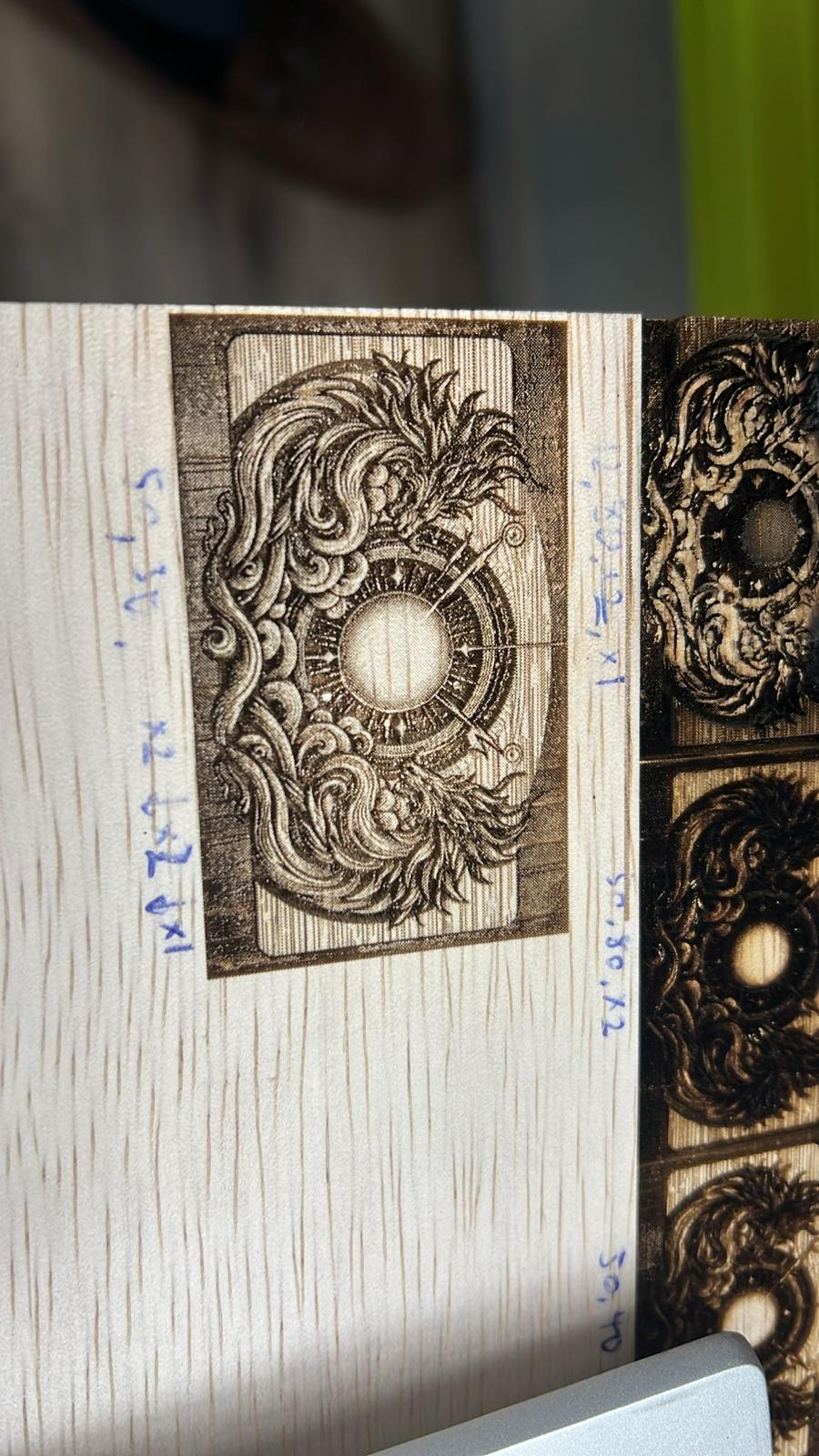
Final Project Integration: A lightbox to entice students to learn Digital Fabrication
People who first start off with Fabspaces, alot of them want to do keychain and gifts. Keychain for 3D printing, keychain for laser cutting, keychain for embroidery...
My side sometimes have a need for students to produce gifts to present to VIPs for their contribution to student's growth. The gift must be aesthetic and looks valuable or creative.
The students who are likes art maybe not be motivated to pick up digital fabrication skills. I also have a group of special needs students who I would like to empower. They are good with arts.
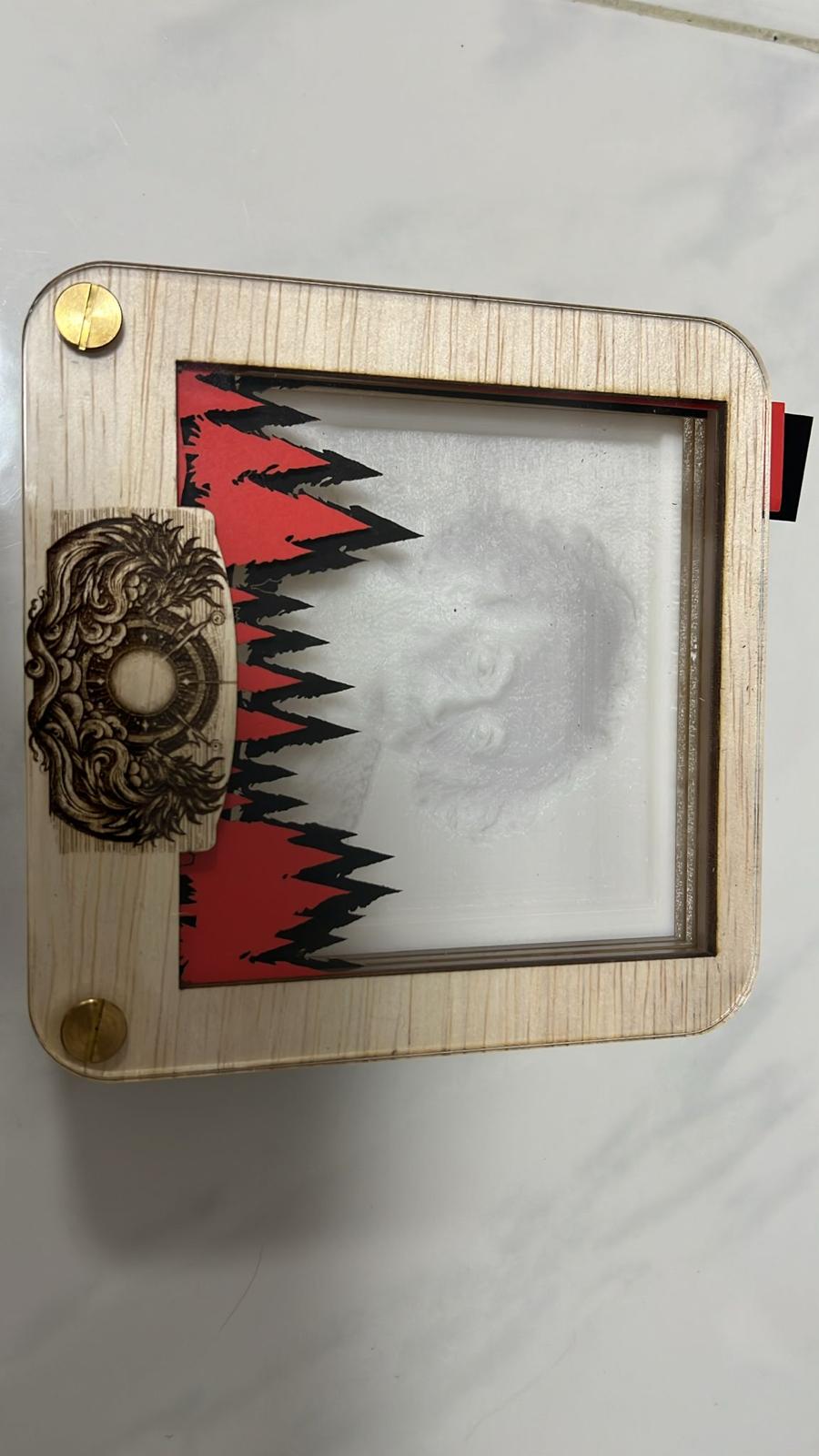
Below is the picture of the lightbox which was done half way in small prototyping steps.

| Question | Answer |
|---|---|
| Empathize | My Stakeholders in this projects are
|
| Define and current solutions |
|
Ideate and reference outside solutions. 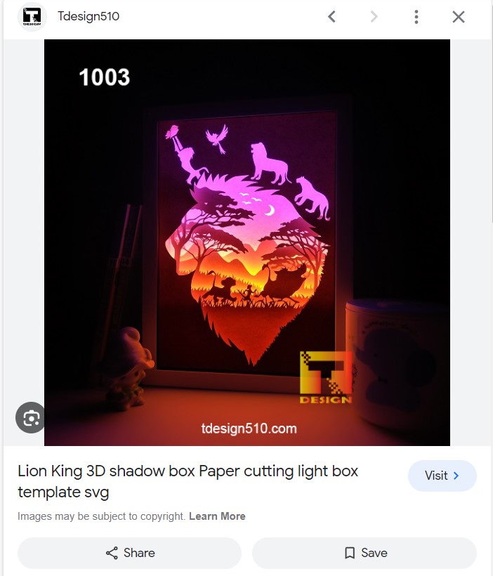 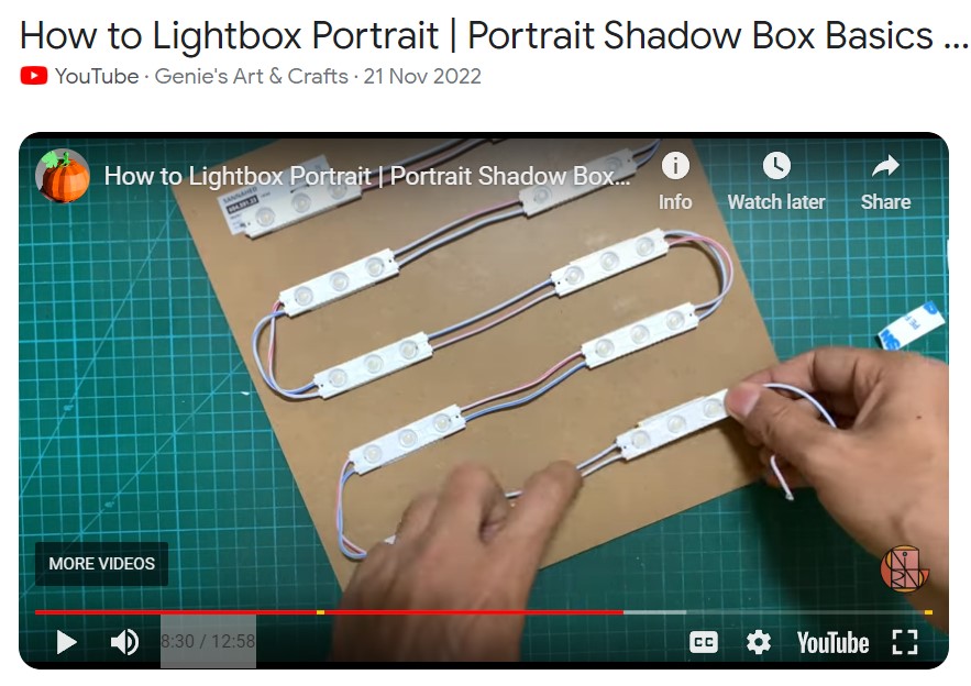 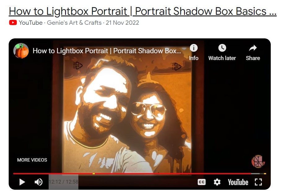 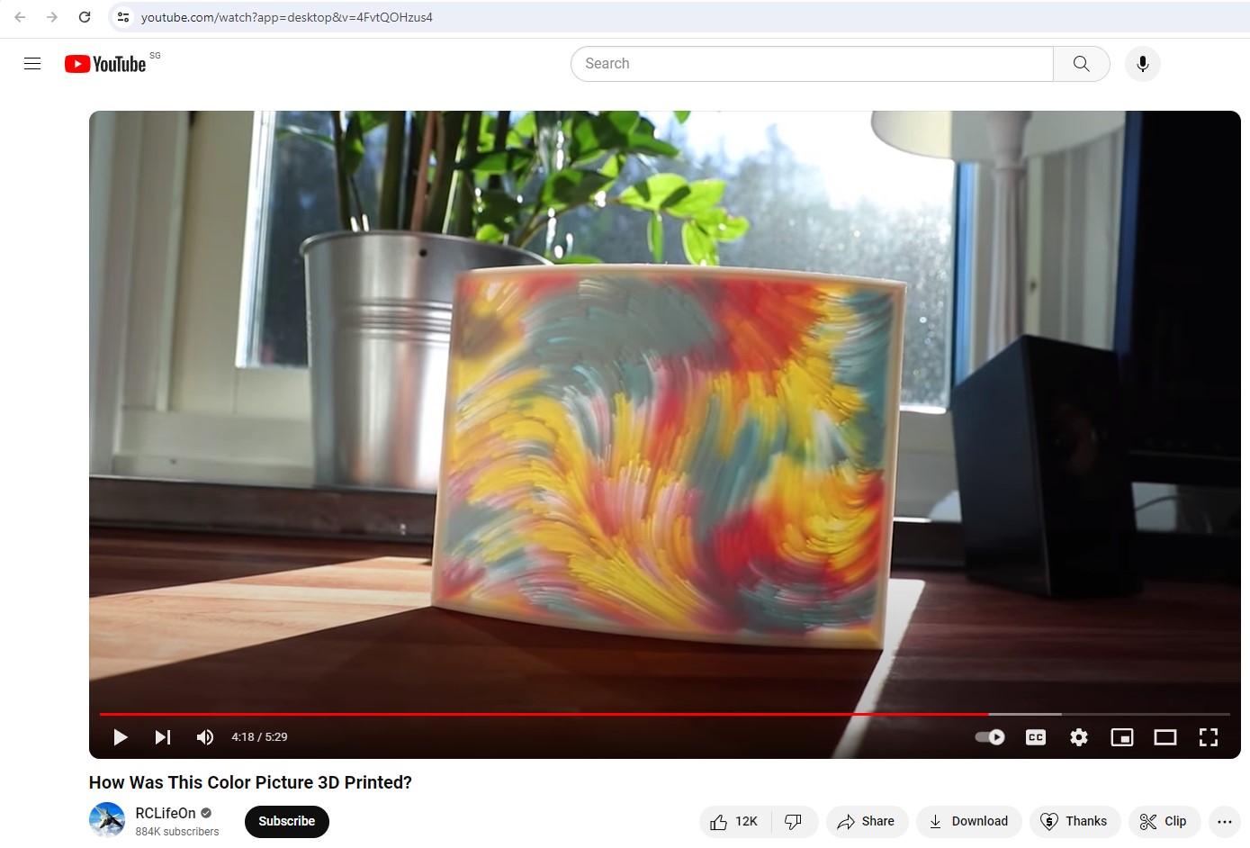 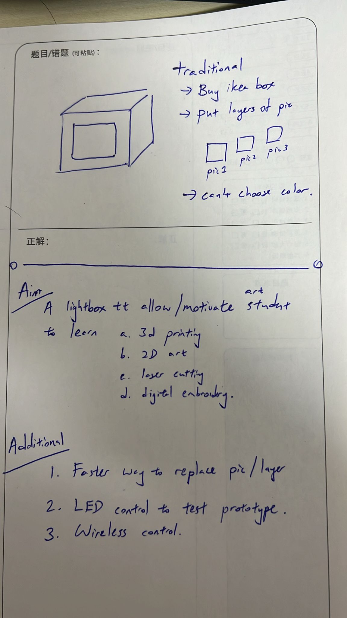 |
A layered lightbox where the student can quickly
|
| What does it do? | A lightbox where students can create their designs and slot their design for rapid correction into the lightbox and then wirelessly control the leds behind to get desired effect post production. Student can use the parametric onshape file to quickly change the sizing. |
| Who's done what beforehand? | Traditional Layered art light box, you have to manually remove all the stack layered to put them together again. |
| What did you design? |
|
| What materials and components were used? | Components include Plywood 3mm, 3mm Acrylic, 220gsm A3 size paper, ESP32C, WSB2812B LED Strip. Materials for the enclosure were primarily PLA for 3D printing, and PCBs for the electronics. |
| Where did they come from? | Sensors and electronics components were sourced from electronics suppliers. PLA was purchased from a local supplier specializing in 3D printing materials. |
| How much did they cost? | The total cost of components and materials was approximately $50 SGD. |
| What parts and systems were made? | Custom PCBs for LED control and Wireless communication, laser cut enclosure, laser work and a software backend for data collection and alert management. |
| What processes were used? | 2D and 3D design, additive (3D printing) and subtractive (laser cutting for PCBs) fabrication processes, electronics design and production, microcontroller programming, and web development. |
| What questions were answered? | - |
| What worked? What didn't? | - |
| How was it evaluated? | - |
| What are the implications? | - |
Prepare a summary slide and a one-minute video showing its conception, construction, and operation. The project incorporates 2D and 3D design, additive and subtractive fabrication processes, electronics design and production, embedded microcontroller design, interfacing, and programming, system integration, and packaging. Where possible, parts were made rather than bought, showcasing individual mastery of the skills required for a complete, independently operable system.
Present your final project, weekly and group assignments, and documentation for a comprehensive evaluation and feedback session.